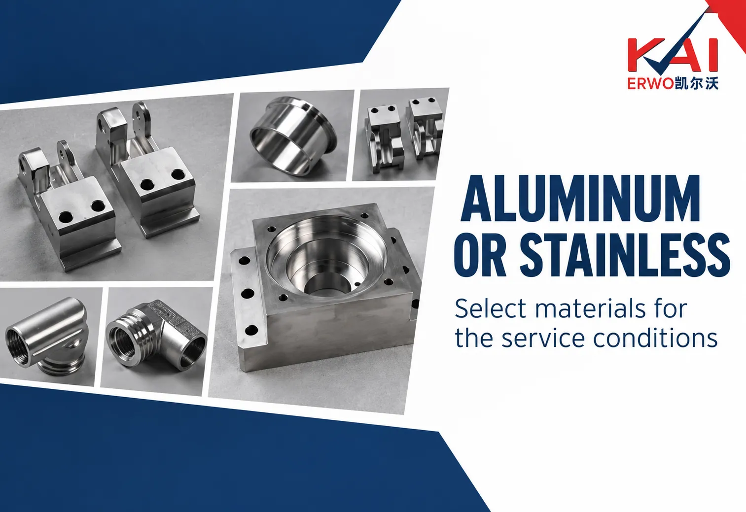
Choose aluminum or stainless steel by examining service exposure, load, mass, stiffness, temperature and joint behavior before comparing machining price. Neither material category is a complete specification. A 6061 aluminum component in a stated temper and a 316L stainless component in a stated product condition have different implications from unspecified aluminum and stainless. The right comparison uses actual candidates and a defined operating environment.
Outokumpu’s Core and Supra product ranges illustrate why stainless selection must distinguish grades rather than treating the family as uniformly corrosion resistant. [1] A cnc machining service company should receive the same level of detail for every candidate material. Ask for manufacturing implications, but keep responsibility for service suitability connected to the design requirements and representative validation.
Define exposure as a set of conditions
An environmental description such as outdoor, marine or washdown is a starting point, not a complete material requirement. Identify the actual fluid or contaminant, concentration where relevant, temperature, duration, wet and dry cycles and opportunities for drainage. Crevices and deposits can create local conditions that differ from an exposed flat surface. Material selection should reflect those local conditions rather than a broad label alone.
Review dissimilar material contacts as part of the assembly. Fasteners, inserts, mating frames and retained fluids can affect corrosion behavior. A machined aluminum bracket may be acceptable in one contact arrangement and unsuitable in another. A stainless substitution does not remove the need to review the surrounding materials. The relevant system includes the joint and the environment, not just the principal component’s alloy name.
Separate the role of a protective treatment from the role of the base material. If the design relies on a coating, consider coverage, handling damage, wear and maintenance. If it relies on the inherent behavior of a stainless grade, confirm that the grade and surface condition are appropriate to the medium. Neither route should be accepted from a generic claim of corrosion resistance without application evidence.
Discuss cleaning and surface contamination where they matter. Manufacturing and handling can affect the delivered surface, and service cleaning can introduce a different exposure from normal operation. State the relevant requirements without inventing a universal cleaning procedure. The supplier can then identify the process and records needed for the specified condition, while the design authority evaluates whether that condition supports the application.
Use representative testing to address remaining uncertainty. Define what the test is intended to reveal and avoid treating a short observation as proof of unlimited life. A test may compare candidate configurations or examine a specific failure mechanism, but its conditions and limits should remain attached to the result. This supports a defensible decision without overstating the evidence.
Compare aluminum and stainless steel by the duty of the interface
Material selection should begin with the operating environment and the limiting failure mode. Aluminum can be attractive where mass, heat transfer or machining effort matters, while stainless steel may suit an interface whose corrosion, wear or temperature requirements justify its different properties and processing cost. Neither material family is a single specification. Identify the alloy and condition, then assess the actual combination of load, contact, moisture, chemicals and service temperature. A general claim that stainless steel never corrodes is not a usable design assumption.
For common austenitic stainless candidates, distinguish grades such as 304L and 316L instead of treating them as interchangeable. Outokumpu’s Core and Supra product information differentiates families intended for different corrosion environments. [1] That is a starting point for selection, not a guarantee for every chloride concentration or crevice geometry. Consider cleaning agents, stagnant liquid and dissimilar metal contact. An aluminum component fastened to stainless steel can require attention to galvanic conditions, drainage and isolation when an electrolyte is present.
Mechanical comparisons need equivalent product conditions. Strength data for a cold worked bar should not be compared casually with annealed sheet data as though they represented the same supply state. Check stiffness, fatigue, thermal expansion and local contact stress where each affects the assembly. A lighter component may allow a larger section that changes stiffness favorably, while a compact contact feature may be governed by wear or bearing stress. The best comparison uses the actual geometry and load path rather than material names alone.
Manufacturing effort can change with the material. Tool geometry, chip control, cutting conditions and finishing strategy must suit the selected alloy. Austenitic stainless steel can present work hardening and adhesion concerns, while aluminum can also suffer adhesion and burrs under unsuitable cutting conditions. [2] Avoid assigning a universal cost multiplier between the families. Ask for comparable quotes using the same geometry, quantity and inspection scope, then examine which operations create the difference. A material that is inexpensive to buy may still be expensive to machine and finish.
Check the effect on neighboring parts before approving a substitution. Mass changes can affect a moving assembly; thermal expansion can change a fit; electrical conductivity can alter a contact design; and a new finish can introduce an additional process. Update drawings, material records and validation plans together. A substitution is an engineering change, even when the external shape remains identical. The decision should preserve the required service behavior while making the manufacturing and procurement consequences visible to the people responsible for accepting the finished component.
Compare the available choices
| Service driver | Aluminum candidate | Stainless candidate | Evidence needed |
|---|---|---|---|
| Low moving mass | Often attractive at equal volume | Higher mass may affect dynamics | Geometry and operating loads |
| Wet chemical exposure | Review alloy coating and couples | Review grade and actual medium | Exposure conditions and compatibility |
| Threaded service joint | Review engagement and repeated use | Review galling and assembly method | Fastener pairing and service procedure |
Specify the material condition as carefully as the alloy
An alloy number is only part of a material specification. Producer data should be read for the stated product form and condition. [3] [4] Product form, temper or heat treatment, thickness and material orientation can affect the properties relevant to a machined component. A drawing that says aluminum while a quotation assumes a readily available plate leaves too much room for substitution. Even a familiar designation such as 6061 should be completed with the required condition and supply form. Ask for the material certificate appropriate to the order and check that its identifiers follow the stock through cutting and machining.
Treat strength, stiffness and resistance to corrosion as separate questions. A higher strength alloy can resist a larger stress before permanent deformation, but changing alloy alone may do little to reduce elastic movement of a geometrically flexible wall. If deflection limits the assembly, examine section thickness, unsupported span and load path before paying for a stronger material. If corrosion controls the decision, identify moisture, salts, cleaning chemicals, dissimilar metals and trapped liquid. A surface that survives dry indoor service may behave differently in an outdoor crevice.
Do not select material from a single typical value copied from a marketing table. Determine whether the value describes a guaranteed minimum, an average laboratory result or an illustrative comparison. Check the exact temper, test direction and thickness range. A certificate for the supplied stock and the applicable procurement specification are more useful for acceptance than a generic alloy summary. Where the design relies on fatigue or fracture performance, obtain the appropriate engineering allowables rather than treating tensile strength as a substitute for those properties.
Material substitutions need an explicit equivalence review. Similar alloy names across national systems are not a universal guarantee of interchangeable composition, product tolerances or mechanical requirements. Ask the proposed mill or stockholder to identify the actual specification and condition. Review the implications for machining, finishing, joining and service. If the substitute changes the coating response or the available stock size, a nominally cheaper purchase can require extra processing and consume the expected saving.
A useful release package therefore records the preferred material, permitted alternatives, required certificates and any orientation restrictions. It also states whether later welding, heat treatment or elevated temperature exposure is expected. These operations can change the material condition that justified the original choice. The purchasing decision should preserve the assumptions used by the designer, while the manufacturing plan should identify when those assumptions need to be checked again. This is a traceability task, not a request for a decorative certificate unrelated to the actual batch.
A hypothetical washdown sensor bracket
Consider a hypothetical bracket that supports a sensor near equipment exposed to washdown. The first design uses aluminum because moving mass is limited. A stainless alternative is proposed after corrosion concerns arise. The engineering team begins by identifying the cleaning fluid, temperature, contact duration, drainage and whether residues remain in crevices. Without those conditions, a general material label cannot resolve the concern.
The team also checks the load path and allowable movement. Changing to stainless at unchanged geometry affects mass and stiffness, while redesigning the section may alter both. The fasteners, mating structure and any insulating or protective measures must be considered as an assembly. If a coating is part of the aluminum proposal, its continuity, damage risk and maintenance conditions belong in the comparison.
Manufacturing quotations then use defined candidate grades and delivered conditions. The test plan includes the relevant exposure and mechanical requirements, with acceptance criteria established by the product authority. This hypothetical example does not declare either family universally suitable for washdown. It demonstrates why environmental detail, joint design and manufacturing evidence must precede a confident material decision.
Define the working thread and the surrounding joint
A thread callout should identify the thread system, nominal size, pitch, required class or tolerance and useful engagement. Blind thread depth needs careful wording because the complete threads available to a screw are not the same as the total drilled depth. The tool requires entry and runout space, and chips need somewhere to go. Check the screw’s actual engagement after washers, brackets and any clearance stack are included. A longer tapped hole does not improve the joint if the selected fastener never reaches the additional threads.
Consider the joint load path before increasing thread length. Pullout resistance depends on material, thread geometry, engagement and the loading condition, while the fastener itself can fail through a different mechanism. Do not apply one engagement multiplier to every aluminum grade or every screw. Repeated assembly, vibration, elevated temperature and maintenance can alter the best choice. An insert may help with wear or serviceability, but it adds a larger prepared hole, an installation operation and new inspection requirements that should be included in the design and quote.
Tapping, forming and thread milling have different constraints. A cutting tap removes material and creates chips; a forming tap displaces suitable material and needs a correctly sized prepared hole; a thread mill follows a controlled path and requires access and interpolation. None is universally superior. Ask the supplier which method suits the material condition, depth, batch quantity and consequences of tool failure. For a small number of unusual threads, flexibility may matter more than the shortest recurring cycle time. For repeated production, tool life and process monitoring become more important.
Surface treatment can change the fit of an internal or external thread. Define whether the thread is masked, processed with allowance or finished after treatment. A coating certificate alone does not establish that a fastener will assemble with the intended fit. Use the appropriate gauging or functional verification in the final delivered condition. Where a thread must provide electrical contact or sealing, clarify those functions separately. Neither a general cosmetic finish nor a simple pass with a thread gauge proves every electrical or sealing requirement.
Make thread inspection meaningful by controlling cleanliness and the condition of the gauge. Burrs at the entrance can produce a false impression of tightness, and excessive force can conceal damage. Check for the right fastener length so that bottoming is not confused with a thread problem. If the joint fails in testing, distinguish stripped material, incomplete engagement, fastener yielding and inadequate preload before changing the machining process. The thread should be designed and verified as part of the assembled joint, not treated as an isolated decorative feature on the model.
Compare the mechanical and manufacturing consequences together
A material substitution changes more than corrosion behavior. At unchanged geometry it can alter mass, stiffness, thermal response and contact behavior. If the geometry is redesigned, those differences can change again. State whether the comparison holds the shape constant or permits optimization. Otherwise, the material that appears preferable may simply benefit from an unstated geometric assumption.
Threaded joints deserve particular attention. Engagement, repeated disassembly, fastener pairing and assembly method can matter differently in aluminum and stainless configurations. Review whether the thread is directly cut in the body or provided by an insert, and consider the space needed around it. An insert can solve one service issue while adding procurement, installation and inspection work. Compare the completed joint rather than only the base material.
Consider thermal mismatch at constrained interfaces. Different materials can expand differently under changing temperature, which may alter clearance or joint load. The significance depends on dimensions, temperature range and constraints. Use appropriate data and a model that represents the actual assembly. A room temperature fit check alone does not establish behavior across a broader service range.
Manufacturing differences should be quoted for the defined alternatives. Cutting strategy, tooling, workholding, deburring and finishing can all change with material. Do not apply an assumed multiplier to an aluminum quote and call it a stainless estimate. Ask the supplier to identify the actual route and included scope for each candidate, then evaluate cost alongside the functional and validation consequences.
Keep the final specification narrow enough to preserve the decision. If the engineering review selected a particular grade and condition, a general order description such as stainless steel can undo that work. List approved alternatives only where their equivalence has been assessed for the relevant requirements. The procurement record should carry forward the conditions that made the material choice acceptable.
Plan a test that can change the engineering decision
A useful validation activity begins with a question and a decision rule. Determine what uncertainty prevents the design or process from being released, then choose evidence that can resolve it. If the concern is fit, an assembly check may be appropriate. If the concern is deflection under load, a dimensional report at rest is insufficient. If the concern is repeatable manufacture, one hand adjusted sample provides weak evidence. Define the test conditions and the action that follows each possible result before running the trial.
Distinguish a hypothetical example, a manufacturer’s recommendation and a verified project result. A calculation can show the direction and approximate importance of an effect under stated assumptions. A tool supplier’s guidance can help select a starting approach. Neither proves the performance of the actual component without relevant verification. Record assumptions explicitly, including material condition, constraints, load and environment. If the test uses a substitute material or simplified geometry, identify which conclusions remain valid and which must wait for the final configuration.
Use representative interfaces. A prototype that fits one specially selected mating part may not demonstrate interchangeability across the permitted dimensional range. Consider the least favorable permitted combination or use a justified sampling plan. For a sealing interface, include the real seal material and relevant surface condition. For a bolted assembly, use the intended joint arrangement and controlled assembly procedure. The test should exercise the mechanism that matters, rather than merely reproduce the visual appearance of the final product.
Document failures without prematurely attributing them to machining. A component that binds may have an unsuitable tolerance stack, an unaccounted coating or a temperature dependent fit even if every manufactured dimension meets its drawing limit. Conversely, a design that is sound on paper can fail because a critical feature was not produced or inspected as specified. Compare the as built evidence with the design assumptions. This separates a product definition problem from a process execution problem and directs the correction to the right owner.
End with a release decision and a record of remaining limitations. Approving a prototype for a fit check is different from approving it for full service loading or long term production. State the scope that the evidence supports and define any further qualification needed. This avoids turning an early successful demonstration into an unsupported performance claim. Validation is valuable when it reduces uncertainty enough to make the next engineering decision responsibly, with a clear understanding of what has and has not been demonstrated.
Evaluate the joint as a material system
A material choice can be undermined by the fastener or mating component. Review the complete joint, including washers, inserts, sealants and any retained fluid. Different contact materials and geometries can change corrosion or wear behavior. The relevant evidence should represent the assembled condition rather than only a coupon of the principal alloy exposed in isolation.
For repeated service assembly, consider how threads and seating surfaces will be used. The joint may require an insert, a controlled assembly procedure or another design change. Each option affects manufacturing and inspection. Avoid solving a service problem by changing the body material alone when the contact mechanism remains unchanged and poorly understood.
Review maintenance assumptions. A protective condition that depends on cleaning or periodic replacement should be compatible with the intended service practice. If the product will be difficult to access, a maintenance dependent solution may be less attractive. These considerations belong in the design comparison because they affect the usefulness of the machined part after delivery.
If a supplier suggests an available substitute, evaluate it against this complete joint description. Similar corrosion descriptions or nominal strengths do not establish equivalence in every contact. Ask for the exact grade and condition, then review the properties relevant to the actual mechanism. Additional testing may be appropriate where the existing evidence does not cover the alternative.
Record the final material decision with its environmental and assembly limits. This helps future teams understand when the choice can be reused and when it needs review. A bracket selected for one cleaning regime or fastener pairing should not automatically be treated as qualified for a different application merely because its external dimensions remain familiar.
A practical review sequence
1. Define exposure, temperature, mechanical loading and limits on mass or movement.
2. Select identifiable grades and conditions for comparison using applicable producer data.
3. Review joints, finish, machining route and inspection for each candidate.
4. Validate the chosen assembly under conditions representative of its intended use.
Common mistakes and better decisions
Stainless is sometimes treated as immune to corrosion, while aluminum is sometimes dismissed without considering the actual exposure and protective design. Both shortcuts ignore the system. Another error is comparing equal volumes when the designs could use different sections. Separate material properties from geometric effects and document whether the comparison assumes unchanged geometry or an optimized alternative.
Frequently asked questions
Is 316L always preferable to 304L?
No. The appropriate grade depends on the environment and other requirements. Additional alloying can be useful in relevant exposures, but it does not guarantee suitability for every chemical or temperature. Use producer guidance and application evidence tied to the actual medium.
Can aluminum replace stainless to reduce mass?
Potentially, but review strength, stiffness, corrosion, wear, temperature and joint behavior. An equal shape substitution may not satisfy the same function. Any redesign should be assessed as a complete material and geometry combination rather than only a density comparison.
Why do stainless threads sometimes seize?
Adhesive interaction can occur under unfavorable material pairing and assembly conditions. Review the fastener combination, surface condition and permitted lubrication or coating. An assembly procedure should address the application; increasing installation torque without diagnosis can worsen damage.
Does a protective finish remove the need to review corrosion?
No. Consider coverage, defects, damage, crevices and contact with other materials. A finish is one part of the design and maintenance strategy. Validate the delivered condition and plausible service exposure rather than assuming an intact coating forever.
Which option is cheaper to manufacture?
It depends on stock, geometry, cutting conditions, tooling, finishing, inspection and quantity. Request comparable quotations for defined candidates. A generic percentage difference between aluminum and stainless machining does not establish the cost of the particular component.
Prepare the next technical discussion
For custom metal parts manufacturing, supply the service environment, candidate grades and conditions, load and mass constraints, drawing, quantity and finishing requirements. Request a DFM and quotation comparison that identifies manufacturing differences while preserving the functional requirements used to judge each material.
References
[1] Outokumpu. Core stainless steel range and Supra stainless steel range. Online product range information, undated; accessed 22 September 2026.
[2] Sandvik Coromant. How to do milling in different materials. Online application guide, undated; accessed 22 September 2026.
[3] Kaiser Aluminum. Sheet Coil & Plate Alloy 6061 Technical Data. Revision 05/06, May 2006.
[4] Kaiser Aluminum. Sheet Coil & Plate Alloy 7075 Technical Data. Revision 05/06, May 2006.